Answer
Nov 10, 2015 - 07:52 AM
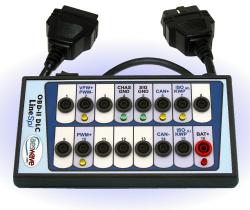
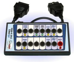
The LEDs provide basic information to help in dataline diagnostics. Most important, the LineSpi provides easy access to the data lines for in-depth signal analysis using a lab scope, logic probe or voltmeter.
There are number of steps you can follow:
1. Check for voltage drop when connecting the scantool:
When the scan tool is connected, do the green LEDs of pin 4 and or 5 and or the red LED of pin 16 change brightness? If the scan tool is in good working order check for resistance problems between the DLC and the wire sources.
2. Scantool does not flash the lights when trying to initiate communication:
When the scan tool is connected it typically starts the process of trying to communicate with the system. The scan tool accomplishes this by trying to communicate with the different OBDII protocols resulting in the appropriate LEDs to flash. If the LEDs do not flash, check the integrity of the DLC connector: Are the pins to the connector in good shape? Are the wires going into the connector damaged? Try the scantool on another vehicle.
3. The scantool attempts communication, the LEDs blink indicating the attempt but no connection:
The scan tool attempts connection but fails – yellow LED flash. Use a lab scope to monitor each data communication line while the scan tool attempts to connect. If you see a flat line at 0v, expect an open circuit or a shorted to ground wire. Use a logic probe to quickly tell if the line is grounded as opposed to simply being 0 volts. A steady high voltage, expect a short to power. On some systems, remove modules until the data line returns to normal.
Source: JM


Add New Comment